Name: Zach Christoff
Date: 4/15/16
Date: 4/15/16
Purpose
To measure Young's Modulus with wire and determine the breaking point while force is applied.
Theory
|
- It is important to understand elasticity before trying to find Young's modulus and the breaking point of brass. The graph on the right represents a stress vs. strain graph. The Elastic Region, as shown by the image, is the only part of the data that is linear. The slope of that line is Young's modulus, or E because:
- E = stress/strain - E = (F/A)/(change in length/original length) - The Plastic Region is the point when the wire stretches beyond return and is unmeasurable with our equipment. Eventually, the wire will reach a breaking point when it cannot handle the force applied, which will be LESS than the max force. ***My data is a little different, however, because I graphed a Force vs. change in length graph. The slope of the line will be used to calculate E. |

|
To calculate Young's modulus, very small measurements had to be made. For instance, the change in length of the wire is too small to measure directly. In order to make that measurement, the device below was set up. A laser would reflect off a mirror and "scaled up" so that a more accurate and precise measurement could be made. The details of the device will be described below.
|
Key Red: laser Dashed red: reflected laser Yellow/gold: brass wire Black line (m): mirror's original position Black dashed line (m'): mirror being moved |

|
|
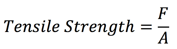
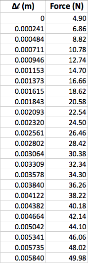
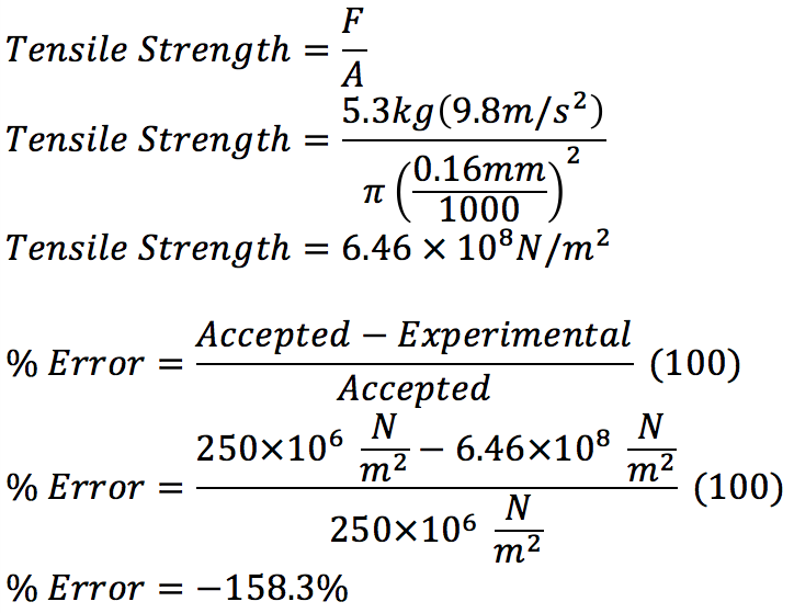
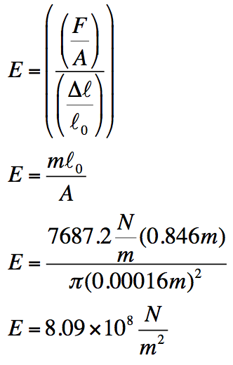
As shown on the right, Young's modulus (E) is defined as stress (F/A) over strain (change in length over original length). I plotted my date in a change in force over change in length graph, so the slope of the line is force over change in length. Therefore, m (slope of the graph) could be substituted in. Since I measured the length and area of the wire, I have all of the components to calculate a value for E. Ultimate strength, or tensile strength, is simply defined by F (force) over A (area). The force is the weight being held by the wire. Weight is (mass x gravity) and area is the cross-sectional area of the brass wire.
|

|
Experimental Technique
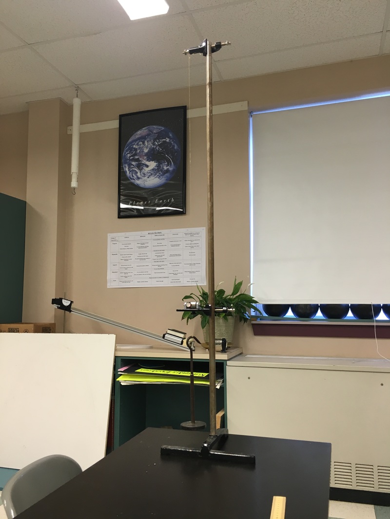
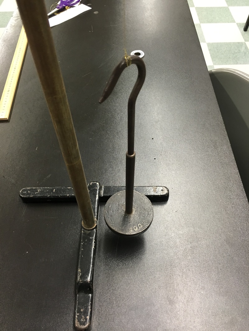
Above shows the apparatus used to add force to the brass wire. Masses of 200g were added to the hook in order to stretch the wire until it eventually broke. The wire was clamped in at the top with a lot of slack in order to reduce the chances of it breaking at the top. Ideally, the wire should break in the middle.
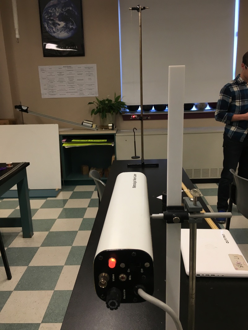
Above is a picture of the laser that was mounted to a stand. It had to be aligned perfectly so that the laser hit the mirror directly in the center. Also, the laser had to reflect back onto the ruler so that measurements could be made. Precautions were taken to ensure the laser was not hitting anyone directly in the eye because it causes permanent damage.
A knot was tied to the top hook to attempt to make the wire break in the middle. A simple knot was first made, then the wire was wrapped around the knot in order to make it more secure. However, my wire did end up breaking near the knot.
|
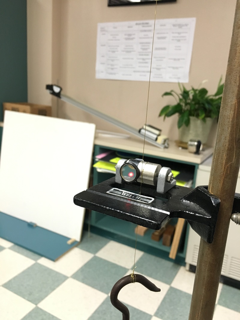
The wire was wrapped around a cylinder that would rotate as the wire stretched. As the cylinder rotated, a mirror that is attached would turn, reflecting a laser back. However, the mirror would have to be reset back to its original position after 4 or so measurements.
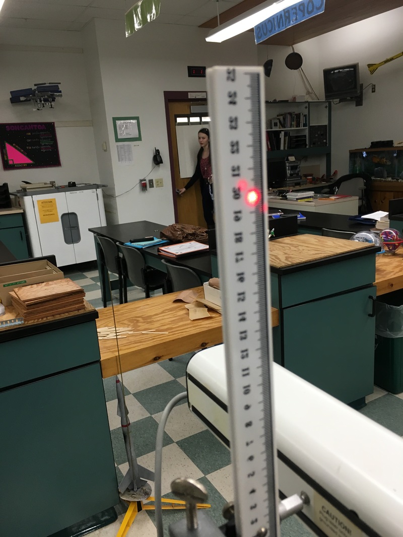
Once the laser was aligned properly, I could begin taking measurements. Every time more force was added to the wire, the mirror would rotate slightly, causing the laser to move down the the ruler. Like stated above, the mirror had to be reset multiple times because the laser would go off the ruler. I simply took note of when I reset the mirror in order to keep the numbers synonymous with my data.
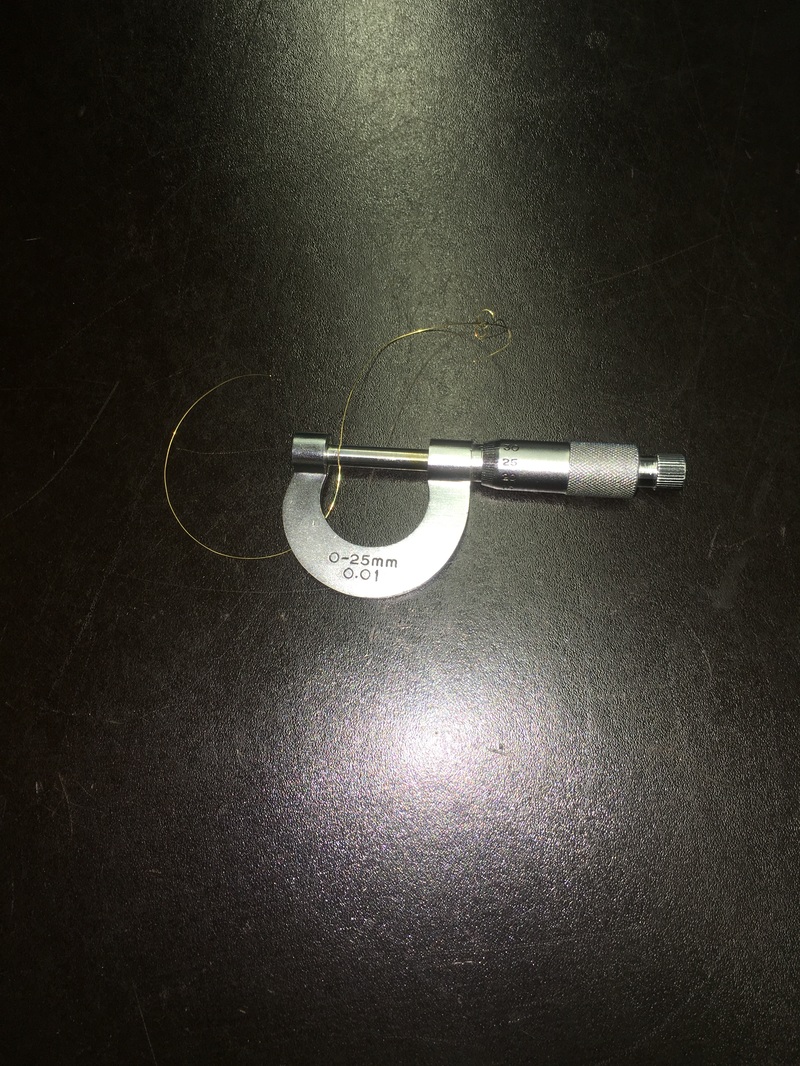
Above is a picture of a micrometer. It was used to measure the thickness of the wire, which is a very, very small number. This measurement would be used in calculations for the area portion of Young's modulus.
|
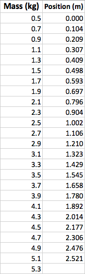
Data
|

|

Analysis
|
Change in Length

Tensile Strength & Percent Error
|
Young's Modulus
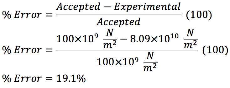
Percent Error for Young's Modulus
|
Conclusion
There were some errors in this lab that contributed to the percent error. For example, L and r where measured after the data was collected. First, the equipment was put away so L was an estimate made based on were I thought the equipment was. Also, r was not measured with the actual wire used in the experiment. It was from the same spool, but the radius could vary since the thickness is so miniscule. The error for the breaking point (158.3% over) is largely due to the fact that I put on too much mass too soon. For instance, the wire was constantly stretching at around 3-4kg, but I kept adding mass for the sake of time. If I had not added the mass, perhaps the wire would have fractured at that mass, which is much closer to its actual breaking point. The error for Young's modulus is most likely due to the mistakes I described above; L and r were not made with the actual experiment equipment and position. Even with all of the mistakes made, and error of 19.1% is fairly decent. However, it could be much improved if the same mistakes were not made.
References
Central Scientific Company, Young's Modulus Apparatus.
Wolfs, F. L. H., and Douglas C. Giancoli. Student Study Guide & Selected Solutions Manual : Physics for Scientists & Engineers with Modern Physics,
Wolfs, F. L. H., and Douglas C. Giancoli. Student Study Guide & Selected Solutions Manual : Physics for Scientists & Engineers with Modern Physics,
